 inglise
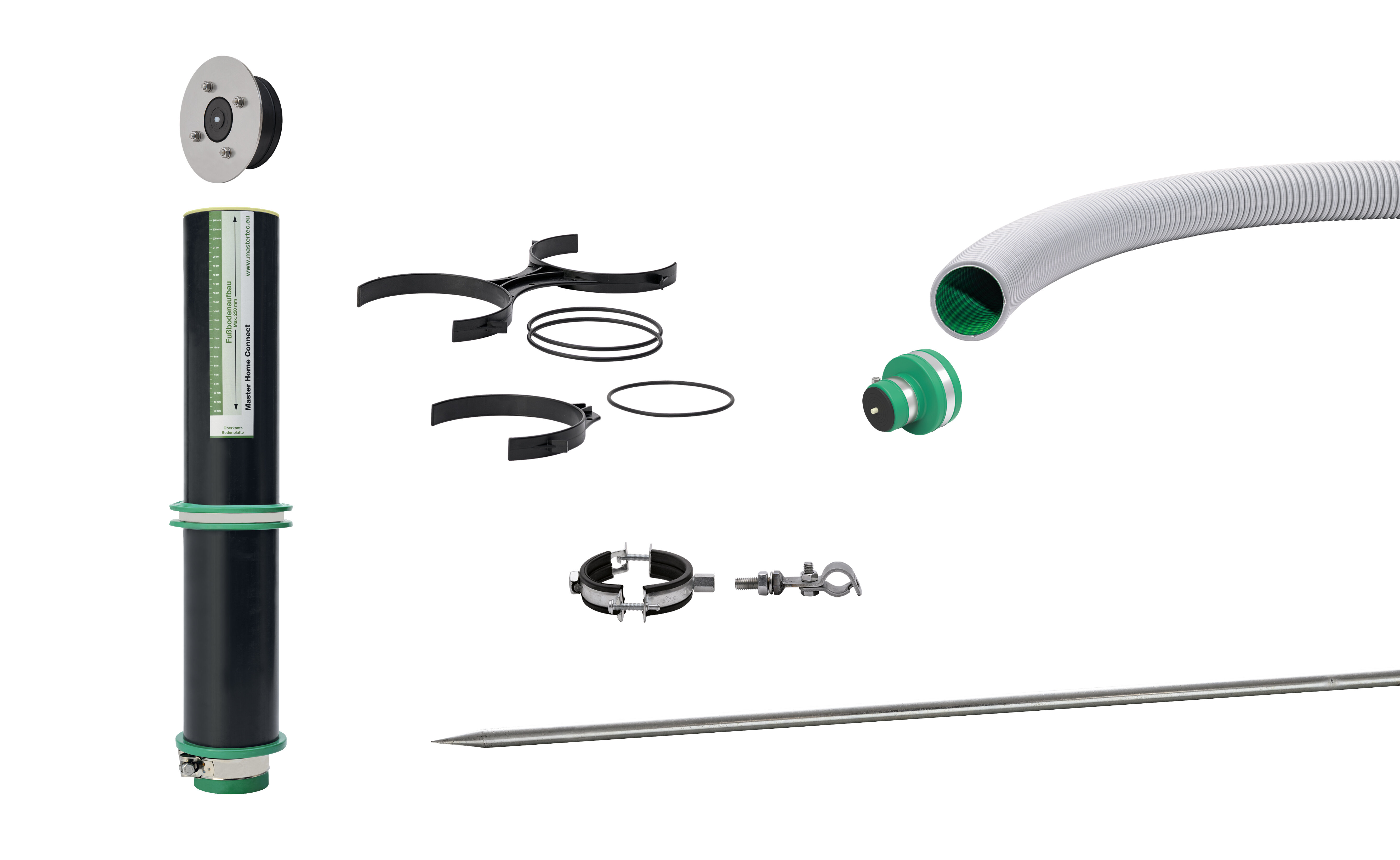
Ühepoolne maja sisselaskeava, mis sobib 4-40 mm kasutustorule - sh 3 m kaablikanal Ø 75 mm
Artikli number 080035


Kõige olulisem teave lühidalt
![]()
- DVGW VP 601 (Chapter 4.5) "Gas and water tightness of the installed house entry)
- Individual components additionally tested for water pressure tightness
- 0,6 m seinamuhv (ehitusaegse kattega), sh seinakrae, pistik ja paigaldusskaala
- MHC tihendussõlm soolo
- Massiivne maanduspiik Ø 20 mm
- Kahekordne keermestatud klamber koos ühendusklambriga
- 1 komplekt MHC-vaheotsakut solo ja duo
- Kaablijuhtme otsakorki solo koos multisisendiga
- 3 m kaablijuhtme Ø 75 mm

Positioning the cable conduit:
The cable protection conduits are routed from the transfer point to the desired insertion position under the floor slab and routed with a bending radius > 350 mm to at least the height of the upper edge of the floor slab.

Fixing the cable conduit:
The cable conduits are connected using the double-threaded clamps at the distance defined for in-line installation. The connection clamp is used to connect the double threaded clamps to the ground spike on both sides. This is driven into the ground before.
The height position of the connection clamp is positioned at min. 400 mm below the top edge of the base plate and fixed using the screws.

Closing the cable condoit / backfilling:
The ends of the cable conduits are sealed with the supplied protective covers.
The trench for the cable conduits can now be backfilled with suitable filling material and compacted in layers.

Installing the MHC lining pipe:
The cable conduits are now cut off XX mm below the top edge of the base plate. The end of the MHC lining pipe fitted with the connector is placed over the end of the cable conduit and fixed in place by tightening the metal clamp.
The vertical position of the lining pipe is not yet relevant at this stage.

Connection of the MHC lining pipes:
The MHC lining tubes are connected to each other using the duo spacer.
To do this, the pipes are clipped into the spacers and fixed in place using the rubber straps supplied.
The spacers are positioned at the height of the upper reinforcement layer.

Underground of the floor slab:
The underground for the floor slab can then be produced in the form of a crushed stone or gravel bedding. When concreting a clean layer, the MHC system must be shuttered off. This maintains the elastic support for later vertical alignment.

Preparation of the floor slab:
The edge formwork of the floor slab is placed.
the reinforcemente for the floor slab is installed.

Vertical alignment / concreting:
The MHClining pipes are aligned vertically after the upper reinforcement layer has been inserted.
The position can be fixed to the upper reinforcement layer via the fixing holes in the spacers using binding wire.
After alignment and fixing, the floor slab can be concreted.

Connection to vapor barrier on the floor slab:
A suitable foil flange seal made of 1.5 mm thick PVC foil is available for the MHC system for integrating the flat vapor barrier on the floor slab.
This is designed at the factory for the 4-fold row arrangement. The foil flange is pushed over the lining pipes from the inside of the building and tightened to the pipe body using tensioning straps
clamped to the pipe body. The flange transition is worked onto the surface seal.
If fewer than 4 lining pipes are used, the foil flange can be cut off on site.

Floor structure:
The planned floor structure, usually consisting of insulation, impact sound protection, underfloor heating if required, screed and top covering, can now be applied.
The length of the lining pipes is designed for a floor structure with a construction height of up to 250 mm. For a visually appealing result, we recommend cutting off the protruding lining pipes at the level of the upper edge of the finished floor.
This can be done before or after installing the floor structure.

Media lines / end caps:
The required end cap is fitted at the end of the cable conduit on the transfer point side.
The media line can then be fed from the transfer point through the cable conduits into the building until it is pulled in far enough.
Solo end cap: 1 media line 4 - 40 mm
Duo end cap: 2 media lines 4 - 25 mm each
The end caps are placed over the cable conduit and over the media lines and fixed in place using clamps

Installing of MHC gasket inserts:
The MHC gasket inserts are finally fitted from the inside of the building:
MHC gasket insert Solo: 1 media line 4-40 mm
MHC gasket insert Multi: up to 2 media lines 2 x 4-25 mm + 2 x 10 mm
Stand: 03.01.2024
Võtke meiega ühendust
Vastame hea meelega teie küsimustele